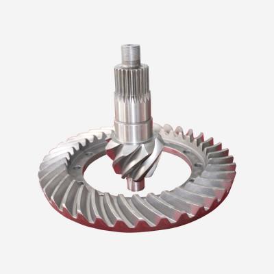
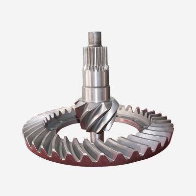
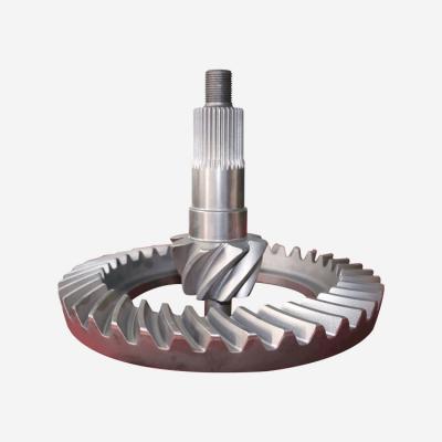
The adjustment problem of the meshing mark of the main drive and driven bevel gear of the main reducer
After adjusting the axial clearance of the driving and driven bevel gear bearings, the meshing clearance of the gears should be readjusted. The meshing gap between the driving and driven bevel gears is usually 0.10-10. .
35mm, the allowable overhaul is 0. .
The use limit is 170mm. .
oomm, if it exceeds the standard, you can make appropriate adjustments under the condition of ensuring normal meshing.
① Adjust the meshing gap between the driving and driven bevel gears, which can be adjusted by moving the positions of the driving and driven bevel gears. For example, it can be achieved by increasing or decreasing the number of adjusting gaskets installed between the reducer casing and the bearing seat of the driving bevel gear (that is, moving the position of the driving bevel gear); or removing the two bearing caps of the driven bevel gear, as required Move the shims of one side cover to the other side to adjust the position of the driven bevel gear, but the total number and thickness of the shims must be kept constant to avoid damage to the adjusted gap between the driven gear bearings.
②-Move to check the meshing condition of the driving and driven bevel gears. It is to check the position of the meshing marks of the gear teeth and use it as the basis for adjustment. The process is as follows:
First wipe the tooth surface, apply medium-viscosity oil paint (such as red lead) evenly and thinly on the tooth surface of the driving (or driven) gear, rotate the driving gear back and forth to make it slightly loaded, and then check the tooth surface Touch the traces to determine if the mesh is working properly. If the meshing is abnormal, the position of the driving gear and the driven gear should be adjusted repeatedly, so that the contact marks on the tooth surface of the driven bevel gear account for 2/3 of the total tooth length, and the distance between the edge of the mark and the small end of the tooth is 2.
-4mm, the distance between the edge of the imprint height and the edge of the tooth surface is 0.8111. .
③ The contact surface and backlash of the driving and driven cylindrical gears cannot be adjusted. When assembling, the meshing position must be symmetrical so that the two cylindrical gears are aligned.
④ Mesh clearance check: If the backlash exceeds 0, adjust the bearing clearance correctly, adjust the gear meshing position,.
8mm (limited to 11mm).
oomm), the gear should be replaced. It is not allowed to change the relative position of the gears to reduce the backlash without taking into account the correct meshing of the gears. When measuring the backlash, use the dial gauge feeler rod to be perpendicular to the large end tooth surface of the driven gear, fix the driving gear shaft, and rotate the driven gear. The reading of the dial gauge is the backlash value. It can also be measured by inserting a feeler gauge into the gap between two gears.