How to adjust the meshing clearance of the driving and driven bevel gears of the main reducer?
Adjustment of the meshing marks of the main and driven bevel gears of the main reducer:
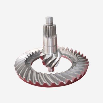
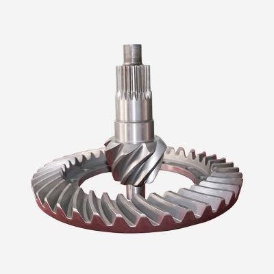
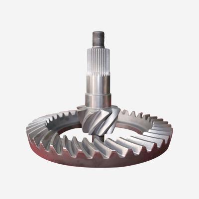
The meshing gap between the driving and driven bevel gears is generally 0.10-10.35mm for new gears, 0.70mm for overhaul, and 1.00mm for service limit. If it exceeds the standard, it can be adjusted appropriately under the condition of ensuring normal meshing.
①Adjust the meshing gap between the main and driven bevel gears, and adjust the positions of the main and driven bevel gears. Such as increasing or decreasing the number of shims between the reducer housing and the bearing seat of the driving bevel gear (that is, moving the position of the driving bevel gear), or removing the two bearing caps of the driven bevel gear, moving one side of the shim to the other side to adjust the driven The position of the bevel gear, but the total number and thickness of the adjusting shims must be kept unchanged, so as not to damage the adjusted driven gear bearing clearance.
②Moving to check the meshing of the main and driven bevel gears is to check the position of the meshing marks of the gear teeth, and use this as the basis for adjustment. The process is as follows: first clean the tooth surface, apply medium-viscosity paint (such as red lead) evenly and thinly on the tooth surface of the driving (or driven) gear, rotate the driving gear back and forth to make it slightly loaded, and then check Contact traces on the tooth surface to judge whether the meshing is normal. If the meshing is abnormal, the position of the driving gear and the driven gear should be adjusted repeatedly, so that the contact marks on the tooth surface of the driven bevel gear account for 2/3 of the total tooth length, the distance from the edge of the mark to the small end of the tooth is 2-4mm, and the height of the mark is Edge 0.8111.6mm.